
Measuring Tools are used to read and transfer distances and angles, in specific units of measure. For woodworking, distances are most commonly measured in either the Imperial (feet and inches) or Metric (millimeters), and angles usually in degrees.
Let's look at the basic measuring tools we use in woodwork.
Tape Measure:

A convenient way to store a long measure. The sliding 'stop' on the end allows internal and external measurements to be made easily. Sadly, the printed scales are prone to wearing off. The curve in width of tape allows for a degree of self-support, but together with the stop, makes accurate use on a flat surface difficult.
 Steel Rule/Ruler:
Available in various lengths, steel rules are a more accurate way to measure and mark out. Good rules have precision etched scales, into which a marking knife or sharp pencil point can be located for accurately taking off measurements. The end of a good steel rule is at ninety degrees to the edges, and at the scale's zero point. This is important for use, and therefore the rule should be carefully looked after. The edges should be straight and parallel.
 Engineer's Try-Square:
Used to check and mark out right angles. The thicker 'stock' can be laid against the straight edge of a component, positioning the thinner 'blade' across the component's face at an accurate ninety degrees.

Used to check and mark out forty five degree angles, in a similar way to the try-square.

Used in a similar way to the try-square, but with an adjustable angle.
The blade slides in the stock, allowing complementry angles to be measured and marked.
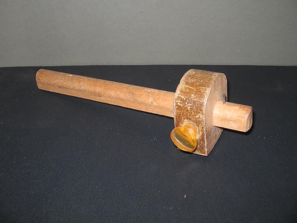
A sharpened pin, in the beam, scores a line a set distance from the stock, which tracks along the workpiece's edge, and can be moved up and down the beam and locked with the thumbscrew.

A circular cutter, on the end of the beam, cuts a line a set distance from the stock, which tracks along the workpiece's edge, and can be moved up and down the beam and locked with the thumbscrew. The one shown has a twist micro-adjustment.

Same as the traditional marking gauge (above), except that the pin is replaced by a pointed out crescent ended knife, held in place by a wedge.

Used to set the slope of dovetails when making out. Different styles and slope angles are available. Steeper slopes are used in hardwood, and shallower slopes in softwood.

A purpose made, single bevel, pointed knife, used to knife marking out lines in wood when accuracy is needed. The single bevel means that these knives are handed.

These bi-metal knives hold there edge longer than standard tool steel marking knives. The knife in the foreground has twin bevels on the one side, allowing it to be used left or right handed.


Useful for laying out circles and arcs, and for stepping off regular increments (e.g. spacing out dovetails).

Much maligned for leaving thick, inaccurate lines as they blunt, pencils do have a place in making out.
Hard pencils can be sharpened to a crescent point to lay in crisp construction lines, or highlight knife lines.
Soft pencils can be used to hatch waste clearly, and can be used for markings which don't damage the surface of the wood.

Practical Applications
Rough Marking Out of components on boards can be done with chalk, crayon, ballpoint pen, or pencil. These markings will all be removed later, as the components are brought to final size. Use templates, rulers, compasses, and flexible battens to guide the marker, or do it freehand. Measurements can be made with the tape measure, leaving everything a little oversize at this stage. Consider things like grain direction and figure when laying out at this stage, as it will be too late once components have been rough cut.
Face Side & Face Edge: Once rough cut, components will usually be prepared with a face side and face edge. A face side is a flat reference on one of the wide sides of a board, prepared using a power jointer, or bench plane. The face edge is adjacent to the face side, straight and flat, and at ninety degrees to it, again prepared using a power jointer, or bench plane. It is from these two reference faces that all of a components dimensions and markings should be made.
Marking for Thickness is usually done using a cutting or marking gauge, where the thickness is fixed. The gauge is set by sliding the stock along the beam until it is the desired width away from the knife edge or pin respectively. The stock is then held tight to the face side, with the knife or pin in contact with the face edge, and then drawn along the edge while the knife or pin scribes a line. Scribing can then be repeated on the reverse face edge, still with the stock against the face side.
Marking for Width is usually done using a cutting or marking gauge, where the width is fixed. The gauge is set by sliding the stock along the beam until it is the desired width away from the knife edge or pin respectively. The stock is then held tight to the face edge, with the knife or pin in contact with the face side, and then drawn along the edge while the knife or pin scribes a line. Scribing can then be repeated on the reverse face side, still with the stock against the face edge.
Marking a Square End is done by using a try-square and marking knife. The stock is set against the face edge, with the blade across the face side, such that the outside of the blade is positioned where the end wants to be. The stock and blade are held tight against the edge and face, while a marking knife is used to knife a line along the outside of the blade. The non bevelled side of the knife should be guided by the square, and held upright so that the cut made is perpendicular to the surface of the work. The bevelled side of the knife will leave crushed fibers on the waste side of the line. If you are using a knife with twin bevels, then you need to hold one bevel flat to the square's blade to achieve the desired result. Failing to do this will result in a 'v' shaped line whose point is not directly in line with the square. The stock is now placed against the face side, and the blade slide up against a knife set in the end of the line. Held firmly, and a line knifed across the edge. This is repeated for the other edge, and then the stock is set back on the face edge, lined up with the same method, and a line knifed across the back side. So long as the component was rectangular in section, these knife lines will all meet up accurately.
Measuring for the Opposite End is achieved accurately by using a steel rule. If the first end has been cut square already, then a flat block is held tight to it's face, forming an abbutment, against which the end of the rule can be located. If not, then a marking knife or chisel can be held upright in the knife line, to the same end. A marking knife is now used to knife a point at the desired distance, and held in place. The try-square can now be positioned accurately by setting the stock against the face edge, the blade against the face side, and sliding the blade up to the marking knife. A knife line can now be made on the face side, and then transfered around the component.
No comments:
Post a Comment
Thank you for taking the time to comment.
Please include as much detail as possible if you require an answer to a question.